Configuring your TOYO TC100 controller for Step and Direction mode is a fundamental step in integrating the unit into your motion control architecture. This guide provides the necessary technical parameters and signal synchronization requirements to establish reliable communication between your controller and the actuator. Follow the step-by-step instructions below to ensure your system is properly set up for precise, responsive performance in your application.
Prerequisites & Safety Warnings
Before proceeding, ensure the actuator is mechanically decoupled from any load or clear of physical obstructions. Reconfiguring control parameters will reinitialize driver behaviors. Verify that you have the TOYO configuration software installed, a compatible USB-to-Serial programming cable, and main DC logic power connected.
Initiate Physical and Software Connection
Connect your PC to the TC100 controller using the dedicated programming cable (RS-232 serial to USB converter). Power up the controller's logic circuit and open the TOYO configuration software on your desktop.
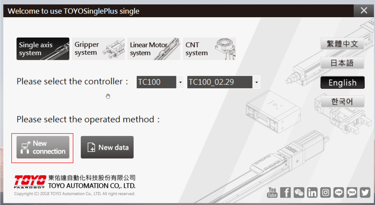
Scan Communication Ports
Scan for active communication COM ports on your computer. The software will detect which serial port is actively connected to the TC100 drive.
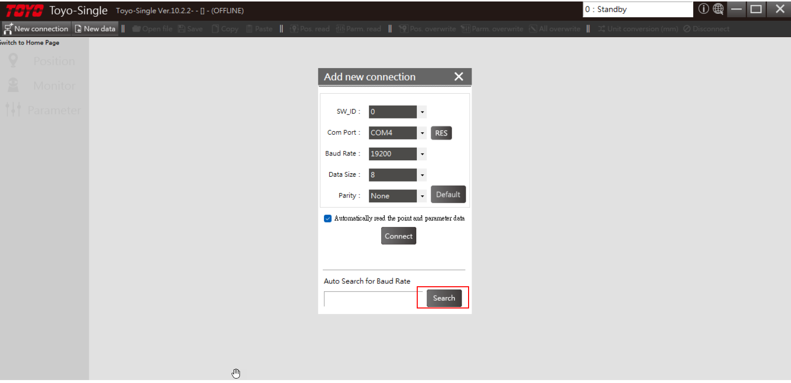
Establish and Confirm Connection
Select the detected COM port matching your connection interface and click to confirm your selection to establish active serial link communication with the controller.
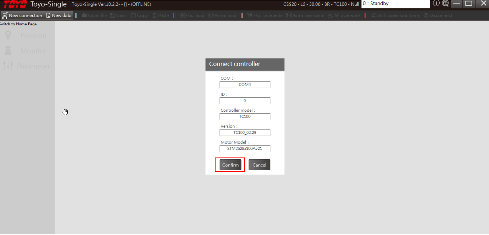
Initialize New Configuration Data
Once communication is established and you are online, navigate to the top utility menu bar and select "New Data" to begin defining a clean parameter setup for the drive.
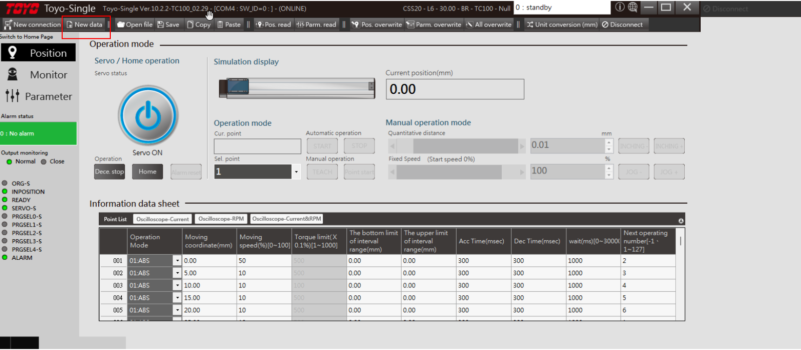
Acknowledge Configuration Warning Prompt
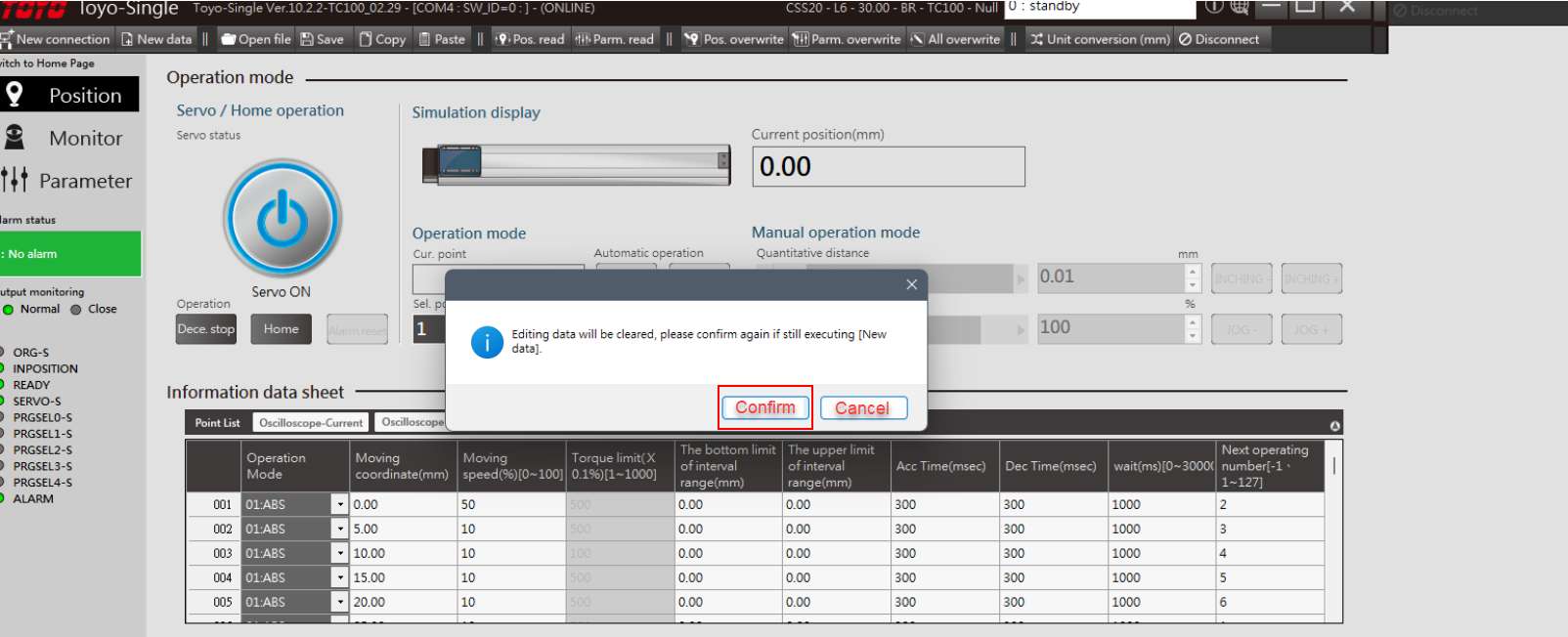
Confirm the popup warning. The system is verifying that you understand your new parameters will overwrite current drive configurations.
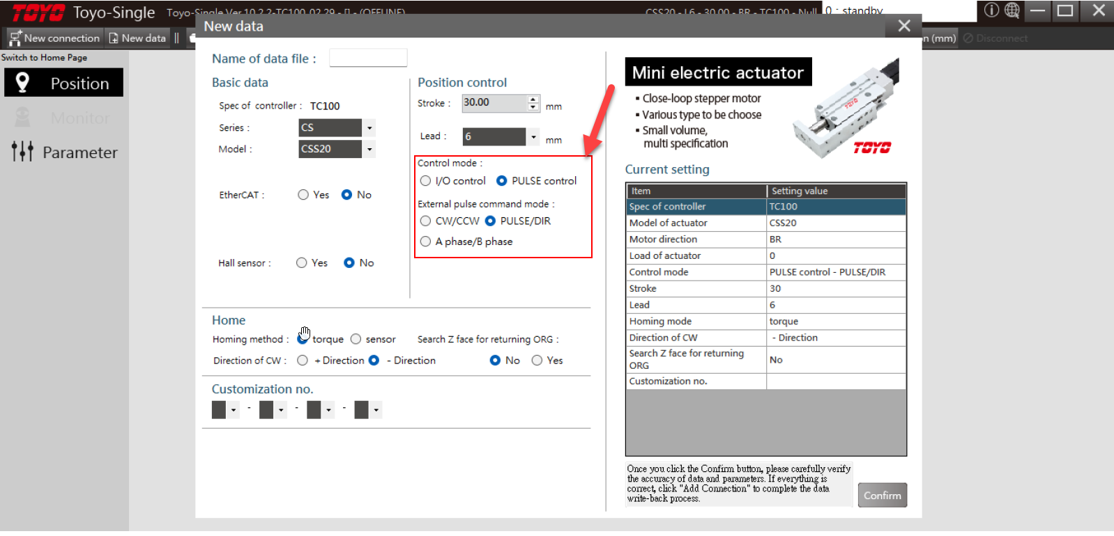
Toggle Control Mode to Pulse Control
Under the drive settings interface, locate the basic operation parameters. Change the system's control mode to Pulse Control (Step & Direction mode).
Execute Drive Power Cycle
Unplug the main DC power connector from the TC100 drive. Wait at least 5 seconds to allow the internal bus capacitors to drain completely, then plug the power cable back in to reboot the drive hardware.
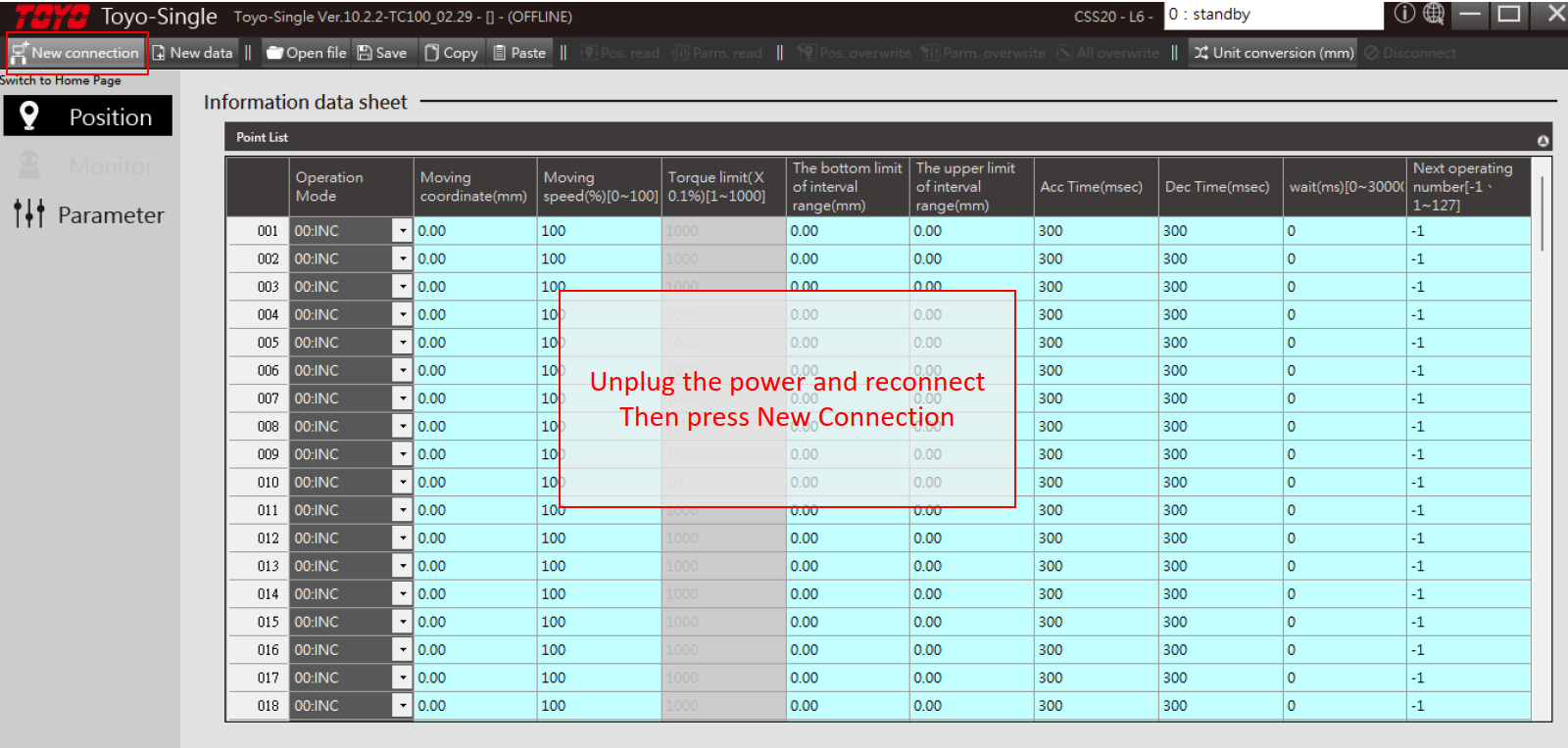
Reconnect to the Cycle-Booted Controller
Re-run the COM port scanning utility and re-establish your connection to the booted TC100 controller.
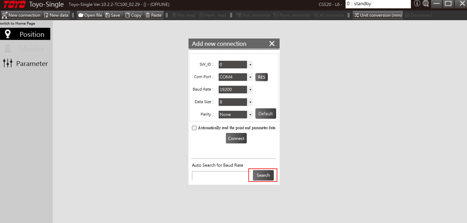
Acknowledge Control Mode Transition
Confirm the software warning notifying you that the connected controller has successfully registered the transition into Pulse Control mode.
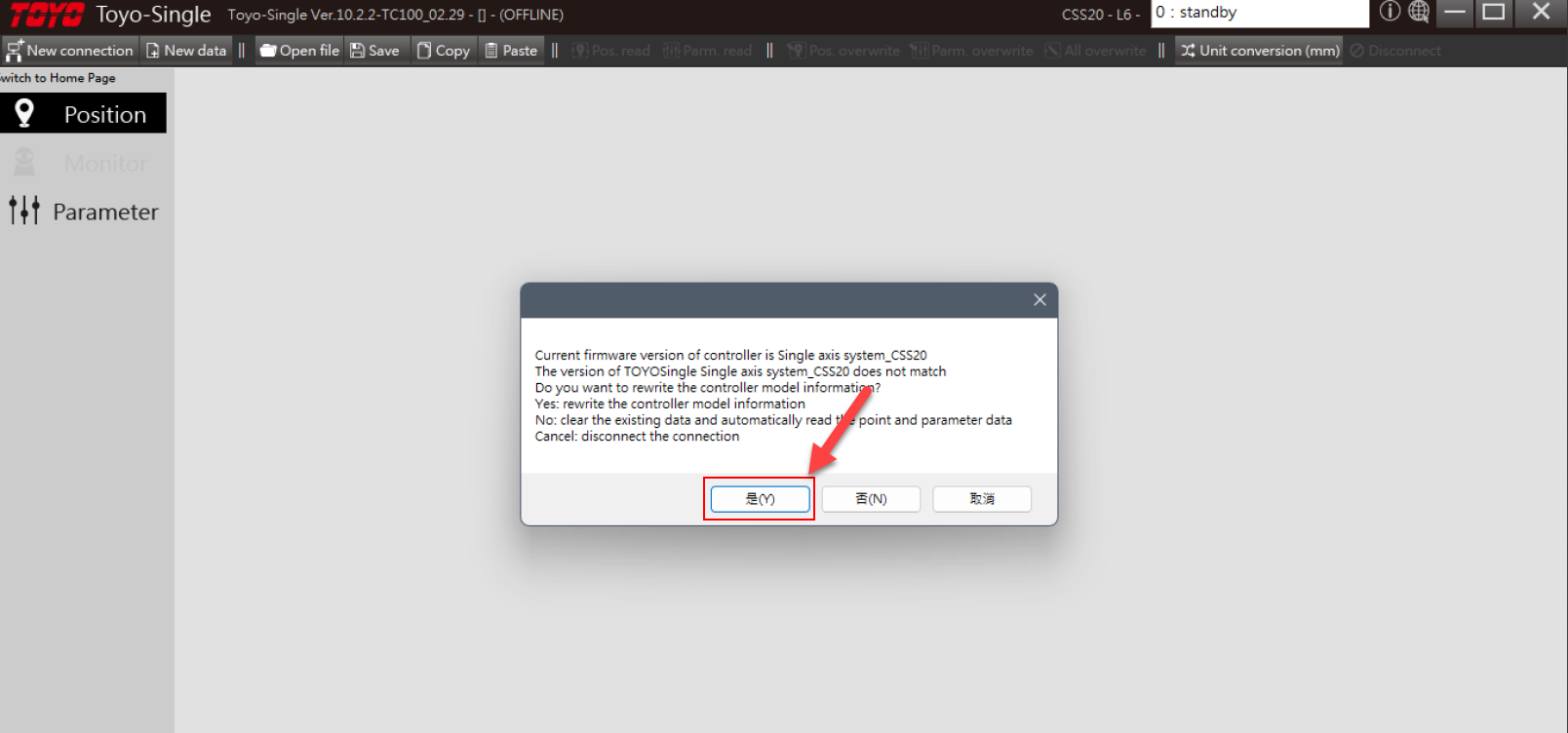
Download Parameters and Overwrite EEPROM
Confirm the operation to overwrite the parameter configurations on the drive. This writes the new Step & Direction operating mode into the controller's non-volatile EEPROM memory.
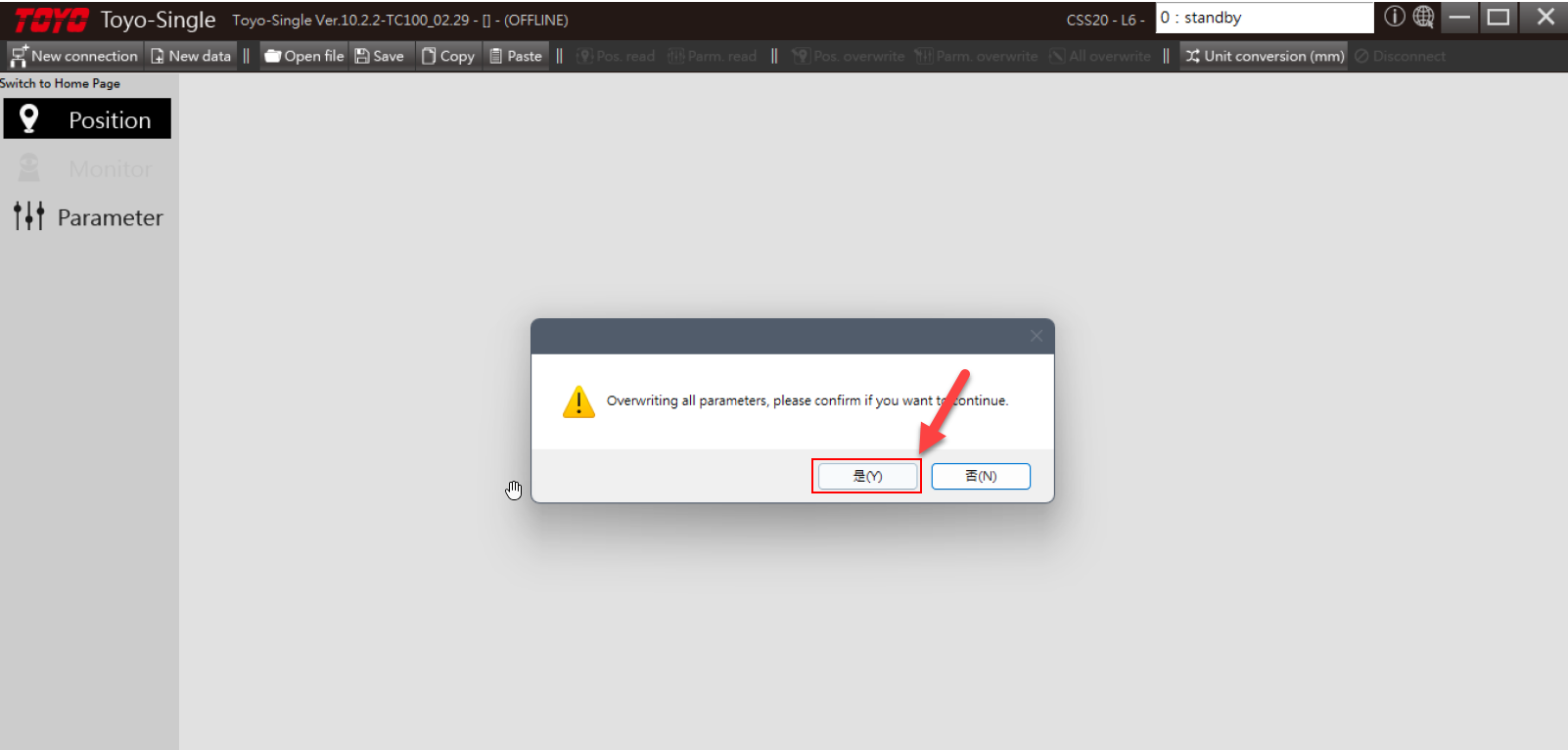
Execute Final Reboot Cycle
Unplug the DC power connector once more to trigger a final hardware reboot, allowing all EEPROM register parameters to properly load and initialize upon startup.
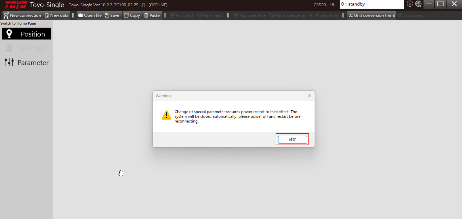
Verify Successful Configuration
Review the controller diagnostics panel. Note that the standard "Jog Control" tab is now hidden or greyed out. This indicates the TC100 is fully locked in Pulse Control mode and is ready to accept physical pulse/direction command signals from your master PLC or motion controller.
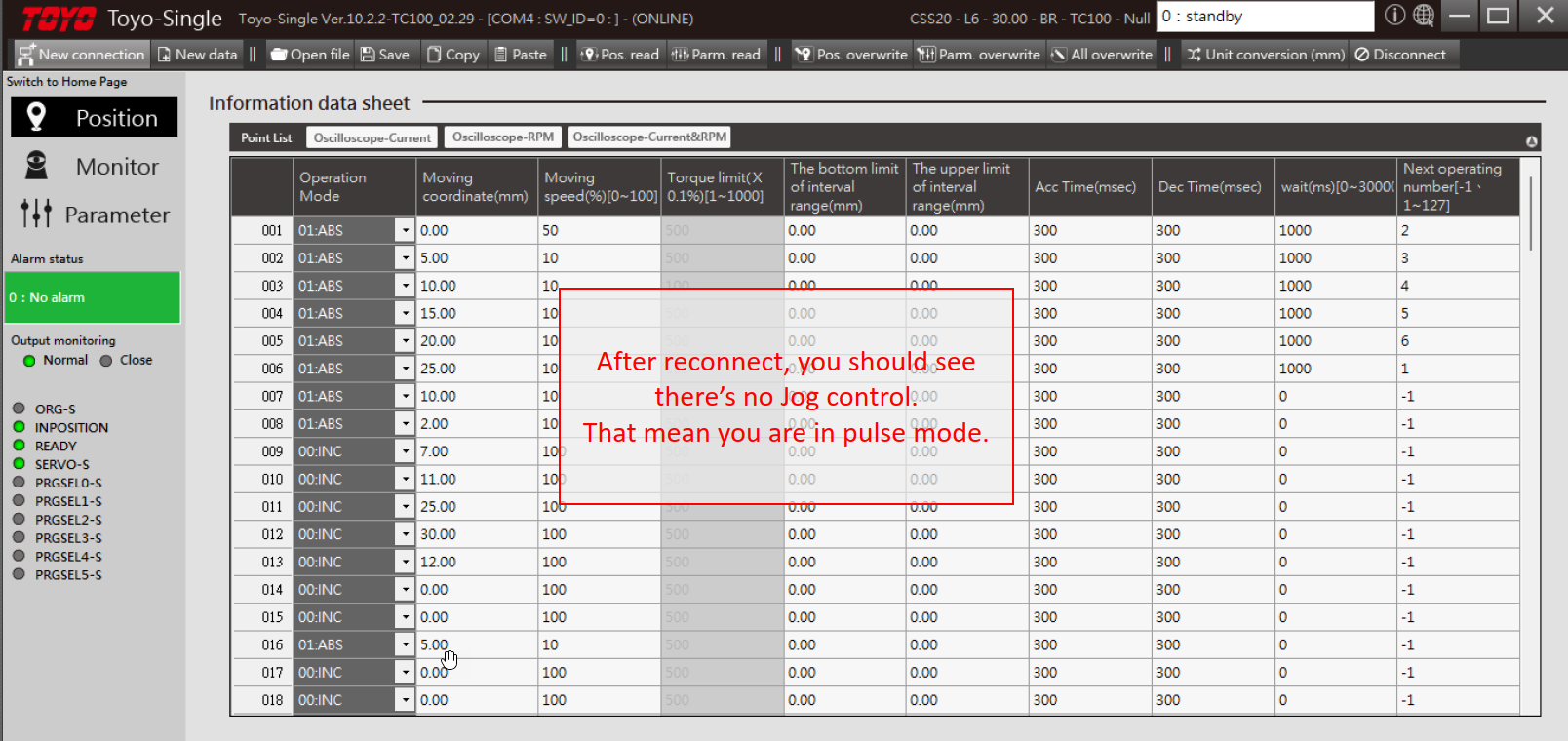
Next Steps for Integration
Now that the TC100 controller is configured to process pulse commands: 1. Signal Wiring: Ensure your pulse and direction input wiring matches standard differential (5V line driver) or open-collector configurations. Add current-limiting resistors if using 24V PLC outputs. 2. Electronic Gearing: Set the electronic gear ratio parameters within the software to calibrate the pulse frequency (pulses/rev) with the lead parameters of your TOYO linear actuator. 3. Motion Profile Testing: Initiate test indexes from your master controller at low speed to verify correct directional behavior and coordinate system alignment.
Need additional technical manuals or CAD drawings? Visit the TC100 Series Product Page or contact our support team at support@toyorobotics.com.